 Tel:
Tel: E-Mail:
 English
 Chinese
 한국어
한국어
 Español


News
The Basic Function – Confirming Position
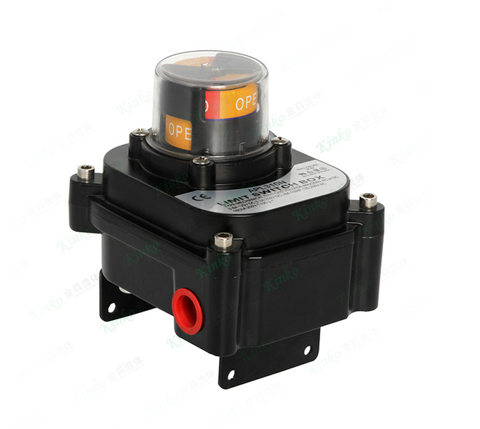
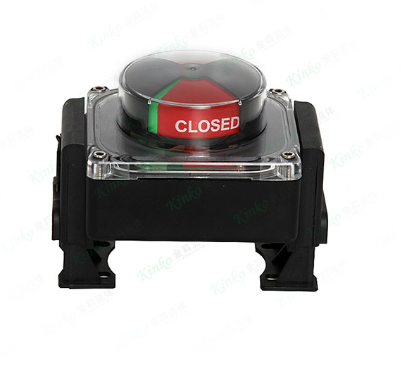
A limit switch assembly (often called a switch box) is mounted on the valve or actuator. It mechanically or magnetically senses when the valve reaches the open or closed position and closes or opens an electrical contact.
The signal tells the control system:
| Signal | Meaning |
|---|---|
| Open contact | Valve is NOT in that position |
| Closed contact | Valve IS in that position |
This simple binary feedback enables:
Sequence logic: Step A cannot proceed until Step B is confirmed
Interlocks: Pumps start only when valves are correctly positioned
ESD verification: Safety systems confirm shut-off valves have closed
Operator interface: HMI displays green/red valve status
Alarm generation: Mismatch between command and feedback triggers alerts
Limit Switch Technologies – Comparing the Options
| Technology | Operating Principle | Advantages | Limitations | Typical Life |
|---|---|---|---|---|
| Mechanical snap-action | Cam rotates a lever that opens/closes contacts | High current capacity; direct switching; simple wiring | Contact wear over cycles; moving parts | 1–5 million cycles |
| Inductive proximity | Metal target enters magnetic field—oscillator circuit trips | No moving parts; unlimited cycle life; sealed | Requires metal target; temperature sensitive; needs power | 10+ million cycles |
| Magnetic reed | Magnet closes a sealed glass-encapsulated contact | Hermetically sealed; immune to dust/oil | Fragile glass; shock sensitive; low current | 1–3 million cycles |
| Hall-effect | Magnetic field changes voltage output | Solid-state; no wear; digital output | Temperature drift; power required | 20+ million cycles |
Selection guidance:
| Application | Recommended Technology |
|---|---|
| Direct PLC input, high current | Mechanical (dry contact) |
| High-cycle service (>500 strokes/day) | Proximity or Hall-effect |
| Dirty/dusty environment | Proximity or reed (sealed) |
| Low-energy circuits (e.g., PLC 24V DC) | Gold-plated mechanical or solid-state |
| Vibration-prone installation | Proximity (no moving parts) |
| Intrinsically safe (IS) | Mechanical or reed (passive) |
Contact Configurations – What the Outputs Mean
Limit switches typically offer one or two sets of contacts per position:
| Configuration | Function | Typical Use |
|---|---|---|
| SPDT (Single Pole Double Throw) | One common, one NO, one NC | Standard feedback—one contact per limit |
| DPDT (Double Pole Double Throw) | Two independent SPDT sets | Redundant feedback or separate interlock |
| Two independent SPDT | Two separate circuits in one housing | One for PLC, one for hardwired interlock |
Contact types:
| Type | Current Rating | Application |
|---|---|---|
| Silver contacts | High (10–20A) | AC control circuits; direct motor switching |
| Gold-plated | Low (100mA–2A) | PLC digital inputs; low-energy circuits |
| Gold-flashed | Medium (2–5A) | General-purpose industrial control |
Critical: Using silver contacts with PLC inputs (typically 5–10mA) will cause oxide buildup and contact failure over time. Always specify gold-plated or gold-flashed contacts for low-energy circuits.
Mechanical vs. Proximity – Detailed Comparison
| Factor | Mechanical | Proximity |
|---|---|---|
| Power source | None (dry contact) | Requires 10–30V DC |
| Output | Contact closure | NPN/PNP switching |
| Cycle life | Limited by spring and lever | Virtually unlimited |
| Shock/vibration resistance | Susceptible to lever damage | Excellent (no moving parts) |
| Temperature range | Wide (-40°C to +120°C) | Limited (-25°C to +85°C typical) |
| Wiring | 2 or 3 wires | 3 or 4 wires (power + signal) |
| Diagnostics | None | Some models offer LED indication |
| Intrinsic safety | Passive—easier to certify | Active—needs IS barriers |
Practical rule: For high-cycle or inaccessible locations, proximity switches justify the added wiring cost.
Mounting and Linkage – The Mechanical Interface
A limit switch is useless if it doesn't accurately track valve position. The mechanical connection matters.
Common mounting methods:
| Method | Description | Best For |
|---|---|---|
| Direct shaft coupling | Switch shaft connects directly to actuator shaft | Rotary actuators; accurate repeatability |
| Cam-operated levers | Cams on a rotating shaft actuate roller levers | Multi-position; adjustable trip points |
| Linear stem connection | Switches triggered by a flag on the valve stem | Linear actuators; rising stem valves |
| Magnetic ring sensor | Ring magnet mounted on actuator piston—sensor on housing | Cylindrical actuators; non-contact |
Linkage best practices:
| Practice | Why |
|---|---|
| Minimize backlash | Lost motion delays feedback—affects sequence timing |
| Use flexible couplings | Prevents binding between shaft and switch |
| Adjustable cams | Allows fine-tuning of trip point after installation |
| Positive-opening mechanism (for safety) | Force-open contacts even if spring fails—required for SIL applications |
Wiring and Electrical Integration
Typical wiring configurations:
| Configuration | Wiring | Application |
|---|---|---|
| 2-wire (mechanical) | Common + NO or NC | Simple PLC input |
| 3-wire (proximity, PNP) | Power (+), ground, signal | Sourcing output (common for European systems) |
| 3-wire (proximity, NPN) | Power (+), ground, signal | Sinking output (common for Asian/US systems) |
| 4-wire (dual contact) | Two independent circuits | Redundant feedback |
Installation tips:
Shielded cable: Required for proximity switches over long runs (>50m)
Terminal labeling: Clear marking (C, NO, NC) reduces commissioning errors
Diodes/suppression: For inductive loads, fit suppression diodes to prevent arcing and PLC damage
Voltage drop: Verify voltage at the switch under load—long cables cause drop that can disable proximity sensors
Special Considerations – Safety and ESD Applications
Positive-opening (forced-open) contacts:
For emergency shutdown and safety-instrumented functions, mechanical limit switches with positive-opening contacts are required per IEC 60947-5-1.
How it works: A mechanical cam physically forces the contact open—even if the contact springs fail
Symbol: Look for a diamond symbol or "direct opening action" in the datasheet
Application: SIL-rated valves; ESD systems; burner management
Redundancy:
| Strategy | Description | Application |
|---|---|---|
| Dual switches | Two independent limit switches on one valve | Voting logic; eliminates common-cause failure |
| Separate cams | Each switch on its own cam surface | Prevents a single mechanical failure from affecting both |
| Separate power supplies | Each switch on different circuits | Prevents single electrical fault from disabling feedback |
Signals and Diagnostics – Beyond Simple On/Off
Modern limit switch boxes may include additional features:
| Feature | Benefit |
|---|---|
| LED indication | Local visual confirmation—reduces field troubleshooting time |
| Diagnostic output | Provides switch health status (wear, cycle count) |
| PNP/NPN selectable | Simplifies integration with different PLC brands |
| Short-circuit protection | Prevents damage from wiring faults |
| Self-monitoring (for proximity) | Detects target presence and internal fault |
Common Failure Modes – And How to Prevent Them
| Failure Mode | Root Cause | Prevention |
|---|---|---|
| Contact failure (mechanical) | Oxide film on silver contacts (low-energy circuits) | Specify gold-plated contacts for PLC inputs |
| Lever fatigue | Excessive actuation force or over-travel | Adjust cams to minimize lever deflection |
| Proximity drift | Target distance changed; thermal expansion | Set gap with 20–30% margin; lock with jam nuts |
| Moisture ingress | Failing seals or missing cable gland | Use IP66/IP68 housing; properly torqued glands |
| Intermittent signal | Loose terminals or vibration | Use spring-cage terminals; apply wire ferrules |
| False trigger (proximity) | Adjacent metal objects or welding spatter | Use shielded cables; keep sensing area clean |
Selection Checklist – Specifying Limit Switches
| Parameter | Questions to Ask |
|---|---|
| Environment | Indoor/outdoor? Chemical exposure? Washdown? |
| Temperature | Minimum and maximum ambient? |
| Cycle frequency | Strokes per day or year? |
| Electrical load | PLC input (mA) or relay (A)? |
| Wiring distance | Distance from switch to control panel |
| Safety function | Is positive-opening required? |
| Actuator type | Rotary or linear? Shaft or stem movement? |
| Mounting space | Limited clearance? Bracket required? |
| Certification | ATEX / IECEx / UL / CSA required? |
Installation Best Practices
Mount securely – Vibration loosens cams and terminal screws
Set cams carefully – Adjust so switch trips just before mechanical stop—not at the stop
Check cable entry – Use glands that seal IP rating; avoid pulling cables taut
Test with power on – Cycle the valve and verify PLC sees correct state
Document settings – Record cam positions and wiring colors for future maintenance
Summary – Small Component, Large Responsibility
Limit switches are among the simplest components in a control system—yet they are critical to safe and reliable operation. They provide the certainty that automated commands have been executed.
Choosing the right technology, contact type, and mounting method—and installing it correctly—ensures:
Reliable sequence execution
Accurate operator displays
Verified safety functions
Minimal troubleshooting downtime
Ivan (Mobile:+86-18968769287)
WhatsApp:+86-13579991606
Wechat:+86-18968769287
Website:www.kinko-flow.com
ZHEJIANG KINKO FLUID EQUIPMENT CO.,LTD

 info@kinko-flow.com
 +86-133 5611 9006

