 Tel:
Tel: E-Mail:
 English
 Chinese
 한국어
한국어
 Español


News
The Performance Gap – What Limits Pneumatic Valves
Without optimization accessories, pneumatic valves commonly suffer from:
| Limitation | Cause | Effect |
|---|---|---|
| Slow stroking speed | Insufficient air flow or undersized supply lines | Delayed process response |
| Jerky motion | Stick-slip from packing friction | Poor control stability; overshoot |
| Short seal life | Dirty or wet air; inadequate lubrication | Leakage; reduced thrust |
| Position drift | Supply pressure fluctuations | Inconsistent flow control |
| Condensation damage | Temperature cycling in humid environments | Corroded internals; electrical failures |
The right accessories address each of these limitations directly.
Seven Accessories That Optimize Performance
1. Quick Exhaust Valves – Increase Stroking Speed
Mounted directly on the actuator port, a quick exhaust valve allows air to vent locally rather than back through the solenoid or positioner.
Benefit:
Reduces exhaust path length—dramatically faster opening/closing
Typical speed increase: 30–60% faster stroke time
Application:
High-cycle on/off services
Emergency shutdown valves requiring rapid closure
Large actuators with long tubing runs
Selection:
Match port size to actuator port
Check flow capacity (Cv) — must exceed actuator requirements
2. Flow Control Valves – Adjust and Dampen Speed
Installed on actuator ports, these valves regulate the speed of air entering or exiting the actuator.
Benefit:
Prevents "slamming" at end of stroke
Reduces mechanical shock—extends valve and actuator life
Allows independent adjustment of open and close speeds
Types:
Bidirectional: Controls flow in both directions (same rate)
Unidirectional: Controls exhaust flow only—allows fast actuation with controlled damping (preferred)
Application:
Any modulating valve requiring smooth travel
Water hammer prevention in liquid services
3. Booster Valves / Volume Boosters – Overcome Pressure Drop
When actuators are located far from the control panel, supply pressure drops due to line resistance. A volume booster amplifies flow without amplifying pressure.
Benefit:
Maintains stroking speed over long tubing runs
Compensates for undersized supply lines
Stabilizes actuator pressure during high-demand cycles
Application:
Large actuators (>100 mm bore)
Remote installations (>50 meters from control panel)
High-cycle operations with frequent full-stroke movement
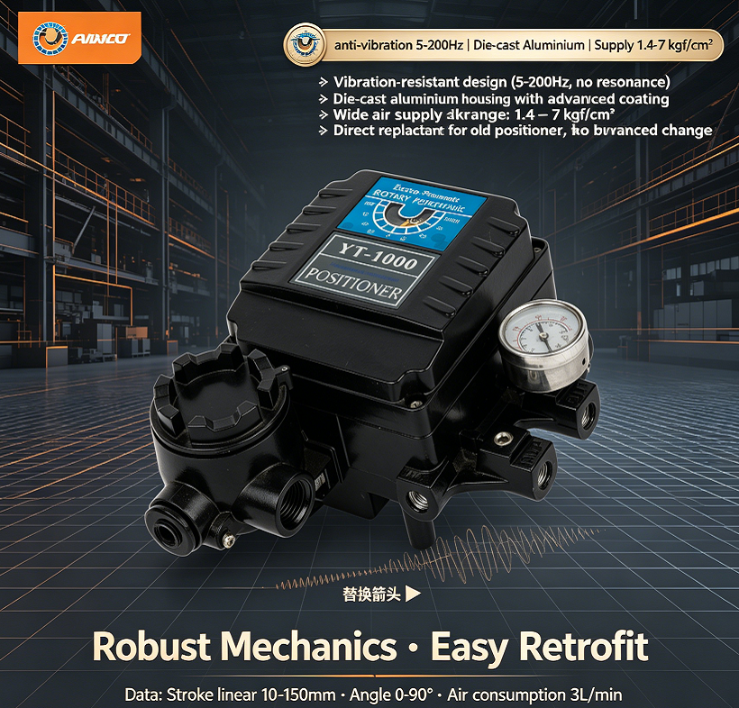
4. Pneumatic Lock-Up Valves – Hold Position on Air Failure
A lock-up valve traps air in the actuator when supply pressure drops below a set threshold.
Benefit:
Holds valve in last position during supply loss (fail-last)
Prevents uncontrolled valve movement during compressor trips
Provides intermediate fail-safe option—neither fully open nor fully closed
Application:
Processes where sudden valve closure or opening is unsafe
Critical modulating loops
Valves without spring-return actuators
5. Air Filter Regulators – Dedicated Supply Conditioning
While the main FRL conditions plant air, a dedicated filter-regulator at each actuator ensures clean, stable pressure at the point of use.
Benefit:
Removes contaminants picked up in distribution piping
Stabilizes pressure despite upstream fluctuations
Prevents positioner and pilot valve clogging
Application:
Every positioner-equipped valve (mandatory)
Outdoor or dusty environments
Recommended filtration: 5-micron or better for positioners; 40-micron for general actuators.
6. Solenoid Pilot Valves – Fast, Reliable On/Off Control
Solenoid valves are the interface between electrical control signals and pneumatic actuation.
Optimization features to specify:
| Feature | Performance Benefit |
|---|---|
| Direct-acting or pilot-operated | High flow capacity for large actuators |
| Manual override | Allows manual actuation during power loss |
| Surge suppression (built-in diode/varistor) | Protects PLC output cards from voltage spikes |
| Low power consumption | Enables use with battery-backed or intrinsically safe systems |
| Encapsulated coil | Prevents moisture ingress—critical for outdoor service |
7. Pneumatic Limit Switches – Position Confirmation
Limit switches provide electrical feedback when the valve reaches open or closed positions.
Optimization consideration:
Mechanical vs. proximity: Proximity switches offer longer life and no contact wear—preferred for high-cycle applications
Adjustable cam: Allows fine-tuning of switch trip point—critical for tight seating applications
Multiple contacts: Enables both PLC feedback and interlock signals from one switch box
Performance Accessory Combinations – By Application
| Application | Recommended Accessory Package |
|---|---|
| High-speed on/off | Quick exhaust + solenoid pilot + flow control (exhaust side) |
| Precise modulating | Positioner + dedicated filter-regulator + volume booster (if remote) |
| Large actuator (>6") | Volume booster + quick exhaust + lock-up valve |
| Emergency shutdown | Solenoid pilot (surge suppressed) + quick exhaust + partial stroke tester (digital positioner) |
| Outdoor / corrosive | Encapsulated solenoids + stainless regulator + IP66/IP68 limit box + heater/thermostat |
| Clean / sterile service | Dedicated filter-regulator + no lubricator + sterile-rated solenoids |
Sizing Considerations – Match Accessories to the Actuator
| Accessory | Sizing Criteria |
|---|---|
| Quick exhaust valve | Port size = actuator port size; Cv ≥ actuator Cv requirement |
| Flow control valve | Port size ≥ actuator port size; adjustable range must cover required speed |
| Volume booster | Supply pressure ≥ actuator requirement; flow capacity matches actuator demand at peak |
| Lock-up valve | Set pressure = 2–3 bar below normal supply; port size ≥ actuator inlet |
| Filter-regulator | Port size ≥ actuator port; flow capacity > peak actuator consumption |
| Solenoid pilot | Cv matches actuator; voltage and power match control system |
| Limit switch box | Contact rating matches PLC input; number of contacts matches function |
Installation Tips – Getting Full Performance
Keep accessories close to the actuator – Especially quick exhaust and flow controls—short lines maximize effectiveness
Use dedicated pressure gauges – At the actuator inlet, not just at the panel—diagnose pressure drop at the load
Orient fittings correctly – Flow control arrows must point in the correct direction—especially for unidirectional types
Provide adequate tubing size – Do not reduce tubing between accessory and actuator—this negates the flow benefit
Install shut-off valves – At each accessory to enable isolation for maintenance without shutting down the entire station
Performance Verification – How to Confirm Optimization
After installing optimization accessories, verify:
| Metric | Target Improvement |
|---|---|
| Full stroke time | Reduced by 20–50% (with quick exhaust or booster) |
| End-of-stroke shock | Smooth deceleration (with flow controls) |
| Position deviation | Within ±1% of set point (with dedicated F-R) |
| Cycle count before failure | 2× to 4× longer (with clean air and correct lubrication) |
| Pressure drop | < 2 psi (0.15 bar) between supply and actuator at peak flow |
Common Mistakes – And How to Avoid
| Mistake | Consequence | Correct Practice |
|---|---|---|
| Installing quick exhaust without flow control | Slamming at end of stroke—mechanical damage | Add flow control on exhaust side for damping |
| Oversizing flow controls | Poor resolution; difficulty adjusting | Match control range to actuator volume |
| Undersizing tubing between accessories | Restricts flow—negates quick exhaust benefit | Use same or larger tubing than actuator port |
| Omitting lock-up valve on critical loops | Uncontrolled valve movement on air loss | Install lock-up for fail-last requirement |
| No dedicated filter-regulator at positioner | Contaminants from main line clog pilot | Always specify point-of-use filtration |
| Plastic fittings in high-vibration areas | Cracking; sudden air loss | Use brass or stainless fittings |
Summary – Accessories Unlock Full Valve Capability
A basic pneumatic valve assembly operates. An optimized one:
Responds faster
Moves smoother
Holds position more precisely
Lasts significantly longer
The incremental investment in performance accessories is repaid through:
Reduced cycle time (production throughput)
Less mechanical wear (lower maintenance)
Fewer unscheduled shutdowns (higher uptime)
Better process control (higher product quality)
Ivan (Mobile:+86-18968769287)
WhatsApp:+86-13579991606
Wechat:+86-18968769287
Website: www.kinko-flow.com
ZHEJIANG KINKO FLUID EQUIPMENT CO.,LTD

 info@kinko-flow.com
 +86-133 5611 9006

