 Tel:
Tel: E-Mail:
 English
 Chinese
 한국어
한국어
 Español


News
What a Positioner Does – The Basic Function
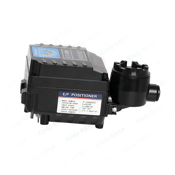
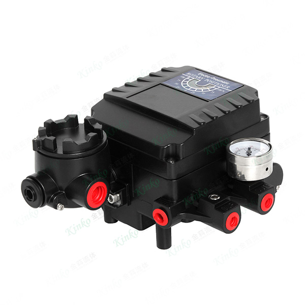
A positioner is a closed-loop controller mounted directly on the actuator or valve yoke. Its core functions:
| Function | Description |
|---|---|
| Signal comparison | Compares input command (e.g., 4–20 mA) to actual valve position |
| Pressure output | Sends corrective air pressure to the actuator to move the valve to the desired position |
| Error elimination | Continuously adjusts until measured position matches command signal |
Result: The valve moves exactly where the control system tells it to—regardless of packing friction, flow forces, or supply pressure changes.
Why a Positioner Improves Control – Key Benefits
| Benefit | Mechanism |
|---|---|
| Eliminates deadband | Mechanical linkages and packing friction are actively overcome |
| Reduces hysteresis | Same command signal yields same position in both directions |
| Compensates for supply pressure drop | Maintains position even if air pressure varies |
| Increases stroking speed | Higher pilot flow accelerates actuator response |
| Enables split-ranging | One positioner can control multiple valves sequentially |
| Provides diagnostics | Internal sensors track deviation, travel, and cycle counts |
Without a positioner: A simple I/P transducer opens the valve proportionally—but friction, wear, and pressure changes cause significant position error.
With a positioner: The valve achieves its commanded position within a small tolerance band, typically ±0.5–1.0% of full stroke.
Types of Positioners – Pneumatic, Analog, and Digital
| Type | Signal | Output | Typical Application |
|---|---|---|---|
| Pneumatic | 0.2–1.0 bar air signal | Boosted air pressure | Hazardous areas; no electrical power available |
| Analog (I/P) | 4–20 mA | Proportional air pressure | General modulating control |
| Digital (Smart) | 4–20 mA + HART / bus | Advanced PID algorithms + diagnostics | Critical loops; predictive maintenance |
Selection guidance:
Pneumatic: Simple, reliable, explosion-proof by nature—but limited diagnostic capability
Analog: Cost-effective for non-critical modulating loops—manual calibration
Digital / Smart: Auto-calibration, remote setup, fault logging, and trend analysis—preferred for critical or safety-related valves
Key Specifications – What to Look For
| Parameter | Why It Matters | Typical Range / Values |
|---|---|---|
| Input signal type | Determines compatibility with control system | 4–20 mA, 0–10V, HART, Profibus, Foundation Fieldbus |
| Supply pressure range | Must match available plant air | 3–15 psi (0.2–1.0 bar) or higher |
| Output pressure range | Must match actuator requirements | 0–100 psi (0–7 bar) typical |
| Stroke range | Must cover valve travel | 0–90° rotary; linear strokes up to 100+ mm |
| Accuracy / linearity | Process control precision | ±0.5% to ±1.0% of span |
| Deadband | Sensitivity to small signal changes | < 0.5% of span for high-performance |
| Flow capacity (Cv) | Determines stroking speed | 0.1–1.5 Cv (depending on actuator size) |
| Environmental rating | Survival in plant conditions | IP66/IP67/IP68; ATEX/IECEx optional |
Digital Positioners – The Smart Choice
Digital positioners offer capabilities beyond basic positioning:
| Feature | Value to Operations |
|---|---|
| Auto-calibration | One-button setup—no manual gain tuning |
| Partial stroke testing | Exercise ESD valves without full closure—meets safety standards |
| Trend logging | Track deviation over time—predict packing or seat wear |
| Friction analysis | Detect increasing stiction before it causes oscillation |
| Travel histogram | Cycle distribution data for maintenance planning |
| Remote configuration | Adjust parameters from control room—no field visits |
| Diagnostic alerts | Send warnings to DCS when deviation exceeds threshold |
ROI: Digital positioners typically cost 30–50% more than analog, but the diagnostic capability reduces unscheduled maintenance by 50–70% in critical services.
Positioner Mounting – Methods and Considerations
1. Direct Mount (on Actuator)
Positioner mounted directly to actuator yoke or top casting
Linkage connects positioner feedback shaft to actuator stem
Best for: New installations; compact footprint
2. Remote Mount (on Valve Yoke)
Positioner mounted on valve body or bracket
Mechanical linkage to valve stem
Best for: High-temperature services (positioner away from heat); tight spaces
3. Integral Mount (Inside Actuator)
Positioner housed within actuator body (linear or rotary)
Best for: Space-constrained or aesthetic installations
Important: Linkage design must be friction-free and backlash-free. Any play in the feedback connection directly degrades control precision.
Feedback Technologies – How the Positioner "Knows" Where the Valve Is
| Technology | Principle | Advantage | Limitation |
|---|---|---|---|
| Potentiometer | Resistive wiper on feedback shaft | Simple; low cost | Wear; temperature drift |
| Hall-effect sensor | Magnetic field sensing | Non-contact; no wear | Temperature sensitivity; hysteresis |
| Rotary encoder | Optical or magnetic pulse counting | High resolution; absolute positioning | Higher cost; complex electronics |
| Inductive LVDT | Linear variable differential transformer | High accuracy; rugged | Higher cost; primarily for linear |
Recommendation: For high-cycle or critical services, specify non-contact sensing (Hall-effect or encoder) to eliminate mechanical wear failure modes.
Tuning the Positioner – Gain, Deadband, and Response
Positioner tuning directly affects loop stability. Common parameters:
| Parameter | Definition | Effect |
|---|---|---|
| Proportional gain (Kp) | Output response per unit error | Higher gain = faster response; too high = oscillation |
| Deadband | Signal change required before output moves | Too wide = sluggish control; too narrow = jitter |
| Integral time (Ti) | Error accumulation for steady-state correction | Eliminates offset; too aggressive causes overshoot |
| Derivative time (Td) | Anticipates error rate | Dampens overshoot; sensitive to noise |
Practical approach:
Start with conservative settings (low gain, wide deadband)
Cycle the valve and observe response
Increase gain until response is crisp—then back off slightly
Adjust deadband to eliminate hunting at steady state
Note: Digital positioners perform auto-tuning that optimizes these settings for your specific actuator and valve.
Positioner vs. I/P Transducer – When to Use Each
| Application | Recommended Device |
|---|---|
| Simple throttling; slow process response | I/P transducer (open-loop) |
| Tight pressure or temperature control | Positioner (closed-loop) |
| Split-range applications | Positioner |
| Valves with high packing friction | Positioner |
| Low-cycle or manual override | I/P transducer (cost savings) |
| Critical or safety-related | Digital positioner with diagnostics |
| Remote or inaccessible locations | Digital positioner with HART/bus |
Common Positioner Issues – Diagnosis and Solutions
| Issue | Likely Cause | Remedy |
|---|---|---|
| Valve hunts / oscillates | Gain too high; deadband too narrow | Reduce gain; increase deadband |
| Valve overshoots | Derivative too aggressive | Reduce Td; lower gain |
| Valve doesn't reach set point | Supply pressure too low; internal leak | Check supply; inspect diaphragm/seals |
| Slow response | Orifice blocked; supply undersized | Clean or replace pilot; increase supply line |
| Erratic position feedback | Loose linkage; worn potentiometer | Tighten linkage; replace feedback device |
| Drifting position | Regulator pressure drift; internal leak | Check regulator; inspect positioner seat |
| No output signal | Electrical fault; I/P coil failed | Check wiring; test coil resistance |
Installation and Commissioning – Best Practices
Mount securely – Vibration isolation protects internal electronics
Linkage alignment – Feedback shaft must rotate exactly with valve stem—no binding
Air supply quality – Feed only clean, dry air (ISO 8573-1 Class 2.4.2 or better)
Signal cable shielding – Use twisted-pair with shield to avoid EMI interference
Calibration – Run auto-calibration (digital) or follow manual stroke procedure
Test full range – Stroke valve from 0–100% and verify feedback matches command at 10% increments
Record baseline – Store calibration values and response times for future comparison
Maintenance – Keeping Precision Over Time
| Activity | Frequency | Purpose |
|---|---|---|
| Check air filter on supply | Monthly | Prevent pilot clogging |
| Inspect linkage and tighten | Quarterly | Eliminate backlash drift |
| Verify calibration | Annually or per site schedule | Confirm accuracy within specification |
| Download diagnostic logs (digital) | Quarterly | Trend deviation; plan maintenance |
| Clean breather port | Annually | Prevent moisture wicking into electronics |
Ivan (Mobile:+86-18968769287)
WhatsApp:+86-13579991606
Wechat:+86-18968769287
Website:www.kinko-flow.com
ZHEJIANG KINKO FLUID EQUIPMENT CO.,LTD

 info@kinko-flow.com
 +86-133 5611 9006

