 Tel:
Tel: E-Mail:
 English
 Chinese
 한국어
한국어
 Español


News
What an FRL Unit Does – The Three Functions
| Component | Function | Why It Matters |
|---|---|---|
| Filter | Removes particulates, water, and oil aerosols | Prevents scoring of spools, sticking of seats, and clogging of pilot ports |
| Regulator | Reduces and stabilizes supply pressure to actuator rating | Prevents over-torque damage and ensures consistent thrust |
| Lubricator | Adds controlled oil mist to lubricate internal moving parts | Extends seal and spool life; reduces friction and hysteresis |
Some applications omit the lubricator (e.g., for instruments or clean service). Others add a shut-off valve and soft-start valve for additional control.
Connection Sequence – Correct Order Matters
The standard flow direction through an FRL is fixed:
text
Compressed Air Supply → Filter → Regulator → Lubricator → Actuator
Why this order?
| Reason | Explanation |
|---|---|
| Filter first | Removes contaminants before they enter regulator—prevents regulator seat damage |
| Regulator second | Receives clean, dry air for accurate pressure control—no particulates interfering |
| Lubricator last | Oil mist must not pass through regulator (oil damages regulator diaphragms and seats) |
Critical: Never install the lubricator before the regulator. Oil in the regulator will cause drift, inaccurate output, and eventual failure.
Connection Methods – Piping Options
1. Direct Mount (Integral)
The FRL components are assembled as a single modular unit—typically with threaded ports on each side.
Advantages: Compact; minimal leak points; factory-assembled alignment
Typical connection: Female threads (BSPP, NPT, or G) on inlet and outlet
Recommended for: Panel-mounted or space-constrained installations
2. Bracket Mount with Tubing
Components mounted separately on a bracket, connected with tubing or hose.
Advantages: Flexible layout; easier component replacement; accommodates larger flow rates
Typical connection: Push-to-connect fittings with nylon or polyurethane tubing
Recommended for: Distributed systems or retrofits
3. Manifold Mount (Multiple Stations)
One FRL supplies multiple actuators via a common manifold.
Advantages: Centralized conditioning; reduced hardware; consistent pressure to all stations
Typical connection: Ported manifold block with individual outlet shut-offs
Recommended for: Valve islands or cluster installations
Port Sizing – Matching Flow Capacity
The FRL ports must match or exceed the actuator's air consumption.
| Actuator Size | Typical Port Size | FRL Port Size |
|---|---|---|
| Small (bore ≤ 50 mm) | 1/8" or 1/4" | 1/4" |
| Medium (bore 50–100 mm) | 1/4" or 3/8" | 3/8" |
| Large (bore > 100 mm) | 1/2" or 3/4" | 1/2" or 3/4" |
Rule of thumb: FRL port size should never be smaller than the actuator port. Undersizing causes pressure drop—especially during high-cycling operations.
Pressure Setting – Adjusting the Regulator
The regulator sets the operating pressure for the actuator—not the supply pressure.
Steps:
Fully close the regulator (turn counter-clockwise until no resistance)
Open the supply shut-off valve
Slowly turn regulator clockwise until the gauge reads the actuator's rated pressure
Cycle the actuator several times—observe pressure drop during stroke
Re-adjust to maintain rated pressure at the peak flow condition
Important: The actuator nameplate pressure is the maximum. Set to the minimum pressure required to move the load reliably—this reduces seal wear and air consumption.
Lubricator Adjustment – Getting the Oil Feed Right
Over-lubrication is as damaging as under-lubrication.
Typical setting method:
Adjust the drip rate to 1–2 drops per 10–15 cycles for intermittent service
For continuous cycling, set to 1 drop per 100–150 strokes
Use the correct viscosity oil—typically ISO VG 32 or 46
Signs of incorrect lubrication:
| Issue | Likely Cause |
|---|---|
| Oil pooling in actuator exhaust | Drip rate too high |
| Actuator feels "dry" or noisy | Drip rate too low or oil type wrong |
| Regulator diaphragm fails | Oil migrating upstream—check order |
Note: Some actuators have self-lubricating seals and do not require a lubricator. Check the manufacturer's recommendation before installing.
Mounting Orientation – Gravity Matters
FRL units must be mounted correctly for proper operation.
| Orientation | Effect |
|---|---|
| Filter bowl downward | Condensate collects at bottom; manual or auto-drain works properly |
| Regulator diaphragm horizontal | Pressure sensing element unaffected by gravity |
| Lubricator bowl downward | Oil wick or sintered element remains submerged for consistent mist |
| Bowl upside down | Drain fails; lubricator starves; regulator drifts |
Always mount with the bowls pointing vertically downward.
Drain Management – Don't Forget the Filter Bowl
Filters collect water and debris. If not drained, contaminants re-entrain into the air stream.
Drain types:
| Drain Type | Application | Maintenance |
|---|---|---|
| Manual drain | Indoor, clean supply | Operator drains daily |
| Semi-automatic | General purpose | Auto-vent when pressure drops |
| Fully automatic (float or electric) | Unattended or remote locations | Self-draining—check periodically |
Recommendation: For outdoor or inaccessible locations, always specify an automatic drain.
Connection Checklist – Before You Turn On Air
| Step | Check |
|---|---|
| 1 | Flow direction arrows match air supply direction |
| 2 | Filter bowl is tight—O-ring seated |
| 3 | Regulator adjustment knob moves freely |
| 4 | Lubricator bowl has oil—fill to indicated level |
| 5 | All threaded connections sealed with appropriate thread sealant (not tape on pipe threads) |
| 6 | Shut-off valve installed upstream for isolation |
| 7 | Gauge(s) installed and readable |
| 8 | Drain valve accessible |
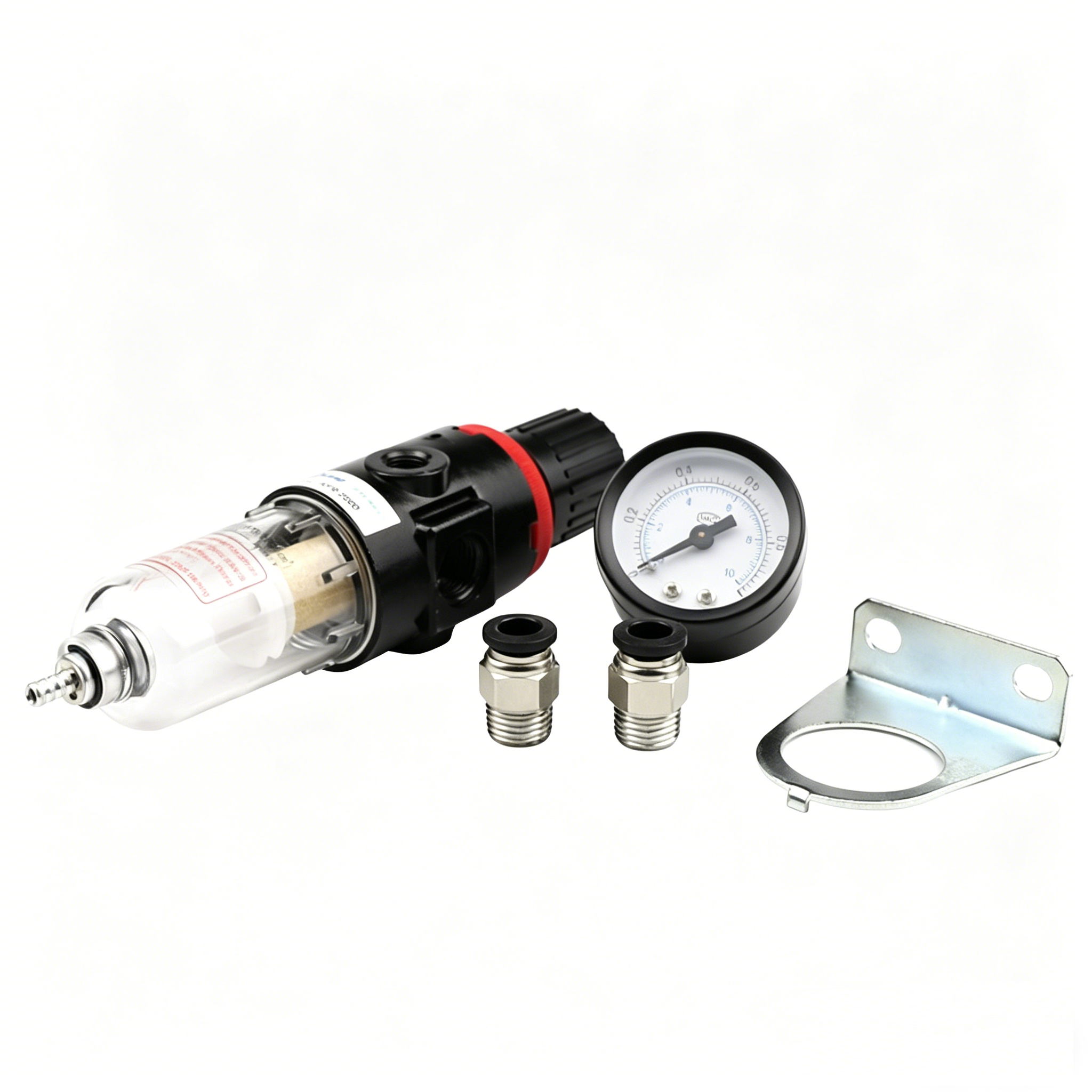
Common Connection Mistakes – And How to Avoid
| Mistake | Consequence | Prevention |
|---|---|---|
| Lubricator before regulator | Regulator oil contamination and drift | Always follow F→R→L sequence |
| Ports undersized | Pressure drop under flow | Match or exceed actuator port size |
| Bowl mounted sideways | Improper water/oil separation | Mount with bowls vertical downward |
| No drain maintenance | Condensate carryover to actuator | Specify auto-drain for remote sites |
| Wrong oil viscosity | Poor lubrication or seal damage | Use actuator manufacturer's recommended oil |
| Over-tightened fittings | Cracked ports or distorted threads | Use torque wrench; follow fitting specs |
| Bypass loop missing | Cannot isolate FRL for maintenance | Install shut-off and bypass valves for critical services |
When to Bypass the FRL – Special Cases
Some applications do not require a full FRL:
| Application | Recommended FRL Configuration |
|---|---|
| Instrument air (ISO 8573-1 Class 1.2.1) | Filter + Regulator only (no lubricator) |
| Clean room or food processing | Filter + Regulator + sterile filter (no oil) |
| Intermittent manual valves | Filter + Regulator only |
| Subsea or remote | Filter + Regulator with auto-drain—no lubricator (to avoid oil depletion) |
| High-cycle production | Full FRL with micro-fog lubricator and auto-drain |
Maintenance After Connection – First 100 Hours
After initial connection and commissioning:
Check filter bowl for water accumulation—drain if needed
Re-tighten fittings—vibration can loosen connections
Verify regulator set point under full flow conditions
Check lubricator drip rate—adjust if too high or low
Inspect for leaks at all threaded joints using soapy water
Document these baseline values for future reference.
Summary – Clean Air Is Cheap; Dirty Air Is Expensive
Connecting an FRL unit correctly is a small task with outsized consequences. One wrong sequence, undersized port, or forgotten drain can lead to:
Sticking actuator spools—erratic valve response
Worn seals—air leakage and reduced torque
Corroded internals—complete actuator replacement
Process upset from valve drift—production loss
Follow the sequence. Match the sizing. Mount with bowls down. Maintain the drain.
Do this, and your pneumatic actuator will deliver its rated performance and service life.
Quick Reference Card – FRL Connection
| Element | Correct Practice |
|---|---|
| Order | Filter → Regulator → Lubricator (never change) |
| Port size | ≥ actuator port size |
| Mounting | Bowls vertical down |
| Regulator setting | At actuator rated pressure, under flow |
| Lubricator setting | 1–2 drops per 10–15 cycles (intermittent) |
| Drain | Manual daily; auto-drain for remote/unattended |
| Thread sealant | Use paste or tape on taper threads—not on straight threads with O-rings |
| Isolation valve | Install upstream for maintenance access |
Ivan (Mobile:+86-18968769287)
WhatsApp:+86-13579991606
Wechat:+86-18968769287
Website:www.kinko-flow.com
ZHEJIANG KINKO FLUID EQUIPMENT CO.,LTD

 info@kinko-flow.com
 +86-133 5611 9006

