 Tel:
Tel: E-Mail:
 English
 Chinese
 한국어
한국어
 Español


News
The Motorized Valve Ecosystem – More Than Just an Actuator
A complete motorized valve system consists of:
| Component | Role |
|---|---|
| Valve body | Flow regulation or isolation |
| Electric actuator | Provides rotational or linear torque |
| Accessories | Enable control, feedback, protection, and communication |
Without proper accessories, the actuator is blind, unprotected, and isolated from the control system.
Six Essential Accessory Categories
1. Position Feedback – Limit Switch Boxes
Provides confirmation that the valve has reached the commanded position.
Why it's essential:
Control systems need actual position—not just the command signal
Enables sequence logic (interlocks, permissives)
Detects valve jamming, seat wear, or actuator failure
Selection factors:
Mechanical or proximity sensing
Number of contacts (typically 2–4)
Visual indicator for local observation
Environmental sealing (IP rating)
2. Torque and Thrust Monitoring – Load Sensors
Measures the actual force applied by the actuator to the valve stem.
Why it's essential:
Prevents over-torque damage to valve trim or actuator gears
Detects increasing friction—early warning of packing or seat wear
Enables "torque-seated" closure for tight shut-off
Selection factors:
Strain-gauge or piezoelectric sensing
Analog output (4–20 mA) for trending
Set-point adjustable trip switches
3. Position Transmitters – Continuous Analog Feedback
Converts valve position into a standard analog signal for DCS/PLC.
Why it's essential:
Modulating control requires continuous position feedback
Enables PID loop closure without a separate positioner
Provides trending data for predictive maintenance
Selection factors:
Output signal (4–20 mA, 0–10V)
Potentiometric or Hall-effect sensing
Mounting style (direct or remote)
4. Heater and Thermostat – Internal Climate Control
Prevents condensation and freeze damage inside the actuator enclosure.
Why it's essential:
Moisture inside the actuator causes electrical failures
Freezing can lock gears or crack housings
Temperature cycling creates "breathing" that pulls in humid air
Selection factors:
Heating power (typically 5–25W)
Thermostat set point (adjustable range)
Low-profile design to fit within enclosure
5. Local Controls – Manual Operation Interface
Allows local open/close/stop commands without a control system signal.
Why it's essential:
Enables commissioning and testing without DCS
Provides emergency manual control during system failures
Allows maintenance isolation without remote access
Selection factors:
Rotary switch or push-button type
Lockable cover to prevent unauthorized operation
LED indication of status
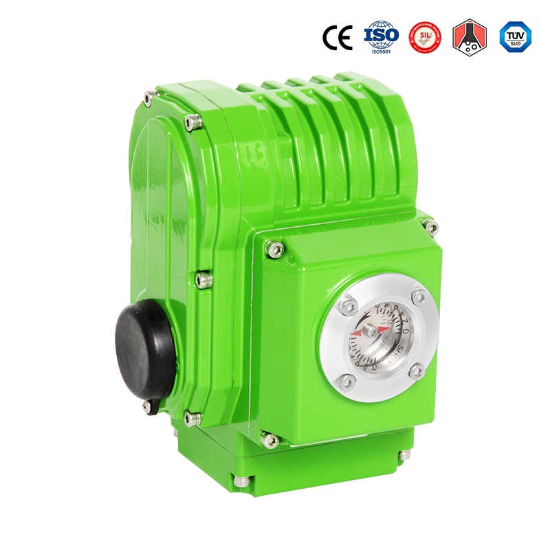
6. Communication Interfaces – Network Connectivity
Connects the valve to plant control networks.
Why it's essential:
Modern plants demand digital communication for diagnostics
Reduces wiring complexity compared to discrete I/O
Enables remote configuration and firmware updates
Common protocols:
Modbus RTU / TCP
Profibus DP / PA
Foundation Fieldbus
DeviceNet
HART (for analog loops)
Protection Accessories – Often Overlooked
Beyond the functional accessories, protection devices significantly extend system life:
| Protection Accessory | Purpose | Cost Avoidance |
|---|---|---|
| Overload relay | Protects motor from thermal damage | Prevents motor burnout—saves actuator replacement |
| Surge suppressor | Absorbs voltage spikes from inductive loads | Protects control boards and position sensors |
| Cable gland kit | Seals cable entries against moisture ingress | Prevents water tracking into electronics |
| Desiccant breather | Absorbs humidity entering through breather ports | Reduces internal corrosion and condensation |
| Anti-condensation heater (as above) | Maintains internal temperature above dew point | Prevents PCB corrosion and short circuits |
Ivan (Mobile:+86-18968769287)
WhatsApp:+86-13579991606
Wechat:+86-18968769287
Website:www.kinko-flow.com
ZHEJIANG KINKO FLUID EQUIPMENT CO.,LTD

 info@kinko-flow.com
 +86-133 5611 9006

