 Tel:
Tel: E-Mail:
 English
 Chinese
 한국어
한국어
 Español


News
Why Positioners Need Maintenance – The Failure Factors
| Factor | Effect on Positioner |
|---|---|
| Dirty/wet air supply | Clogs pilot nozzles; corrodes internal parts; sticks spool valves |
| Vibration | Loosens linkages and terminal screws; drifts calibration |
| Temperature cycling | Causes condensation inside housing; degrades O-rings |
| Packing wear (valve) | Increases friction—positioner works harder; deviation increases |
| Electrical surges | Damages I/P module or circuit board (on smart models) |
The payoff: A properly maintained positioner lasts 8–10 years in typical service. Poor maintenance can reduce that to 2–3 years.
Maintenance Intervals – Recommended Schedule
| Task | Frequency | Who |
|---|---|---|
| Visual inspection | Monthly | Operator / Technician |
| Air filter check / drain | Monthly | Technician |
| Linkage inspection | Quarterly | Technician |
| Calibration verification | Annually (or per site schedule) | Instrument Technician |
| Full overhaul (seals, cleaning, recalibration) | Every 3–5 years (or per cycle count) | Qualified Technician |
| Diagnostic download (smart models) | Quarterly | Engineer / Technician |
Adjust frequency based on environment:
| Environment | Recommended Interval Multiplier |
|---|---|
| Clean, indoor, climate-controlled | 1× (standard) |
| Outdoor, moderate | 1.5× |
| Dusty / dirty | 2× |
| Offshore / salt spray | 2× |
| High vibration | 2× |
Monthly Maintenance – Visual Inspection and Air Supply
1. Check air supply quality
| Check | Acceptable Condition | Action if Not |
|---|---|---|
| Filter-regulator bowl | No water/condensation; clean element | Drain; replace element |
| Supply pressure | Within positioner rated range (typically 3–7 bar) | Adjust regulator |
| Air line leaks | No audible leaks; soapy water test passes | Tighten or replace fittings |
| Oil content | No oil mist visible in exhaust (for smart units) | Check upstream filter; replace if needed |
2. Visual inspection of the positioner
| Item | What to Look For | Action |
|---|---|---|
| Housing | Cracks, corrosion, or discoloration | Assess for replacement; check environmental protection |
| Cable entry | Gland tight; no moisture or dirt at entry | Tighten; re-seal if needed |
| Terminal cover | Secure; no missing screws | Tighten; replace screws if missing |
| Label / nameplate | Legible; not degraded | Replace if unreadable |
| Exhaust port | Clear; not blocked by dirt or ice | Clean; check breather if fitted |
| Local display (if fitted) | Readable; no condensation inside lens | Dry; replace cover seal if fogging occurs |
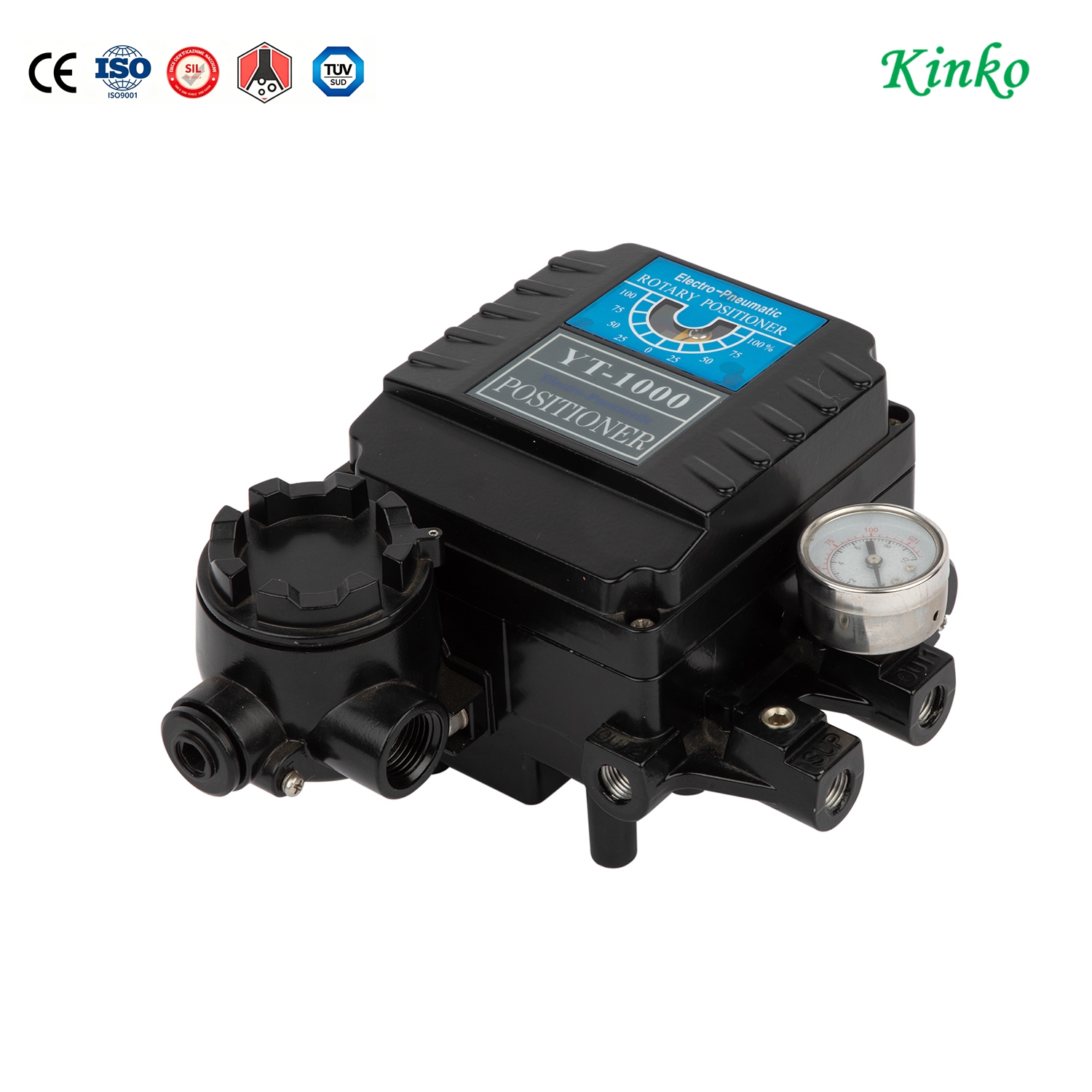
Quarterly Maintenance – Linkage and Mechanical Inspection
1. Linkage inspection
The mechanical feedback link between valve stem and positioner is the most critical connection.
| Check | Acceptable | Action |
|---|---|---|
| Linkage tightness | No play or looseness at pivot points | Tighten all screws and lock nuts |
| Linkage wear | No visible wear marks or elongation at pin holes | Replace worn linkage components |
| Range of motion | Positioner feedback shaft rotates full range without binding | Clean or lubricate pivot points (dry lube only) |
| Alignment | Feedback shaft parallel to valve stem travel | Realign bracket if misaligned |
2. Zero and span check (without recalibration)
Cycle the valve fully open and fully closed—verify that the positioner output matches the input signal.
| Signal | Expected Position | Action if Deviation > 2% |
|---|---|---|
| 4 mA (or 0%) | Fully closed | Calibration required |
| 20 mA (or 100%) | Fully open | Calibration required |
| 12 mA (or 50%) | Mid-stroke | Calibration required |
Annual Maintenance – Full Calibration Verification
Tools required:
Calibrated current source (4–20 mA)
Precision pressure gauge (0–100 psi range)
Multi-meter (for feedback signal check)
Hex keys and screwdrivers
Manufacturer's calibration procedure
Basic calibration procedure:
Isolate and prepare
Shut off air supply; lock out/tag out if needed
Remove cover; access zero/span adjustments
Connect calibration current source to input terminals
Zero adjustment (4 mA / 0% position)
Apply 4 mA (or minimum signal)
Adjust zero screw until valve reaches full closed position
Verify with mechanical stop or limit switch indication
Span adjustment (20 mA / 100% position)
Apply 20 mA (or maximum signal)
Adjust span screw until valve reaches full open position
Re-check zero—adjust if interaction occurs (repeat until stable)
Verify linearity
Apply 8 mA, 12 mA, 16 mA
Check position at each step—deviation should be within specified accuracy
Record values for trending
Restore and document
Replace cover; restore air supply
Cycle valve 2–3 times; verify repeatability
Document settings and date for next calibration
For smart/digital YTC positioners: Use the auto-calibration feature if available—follow manufacturer's handset or software procedure instead of manual screw adjustment.
Smart Positioner Diagnostics – Leverage Digital Data
If your YTC positioner is a smart model with communication capability, use it as a maintenance tool:
| Diagnostic Parameter | What It Indicates | Action |
|---|---|---|
| Travel deviation | Increasing deviation = packing wear or friction increase | Schedule repacking |
| Friction trend | Rising friction = dirt or seal degradation | Inspect and clean |
| Response time | Slower response = pilot issues or supply problems | Check air supply; clean pilot |
| Cycle count | End-of-life estimation | Plan preventive replacement |
| Supply pressure trend | Dropping pressure = filter blockage or regulator drift | Replace filter; check regulator |
| Temperature logs | Outside operating range | Check enclosure; add insulation or cooling |
Best practice: Download diagnostics quarterly and compare with baseline. A consistent upward drift in deviation is your best early warning.
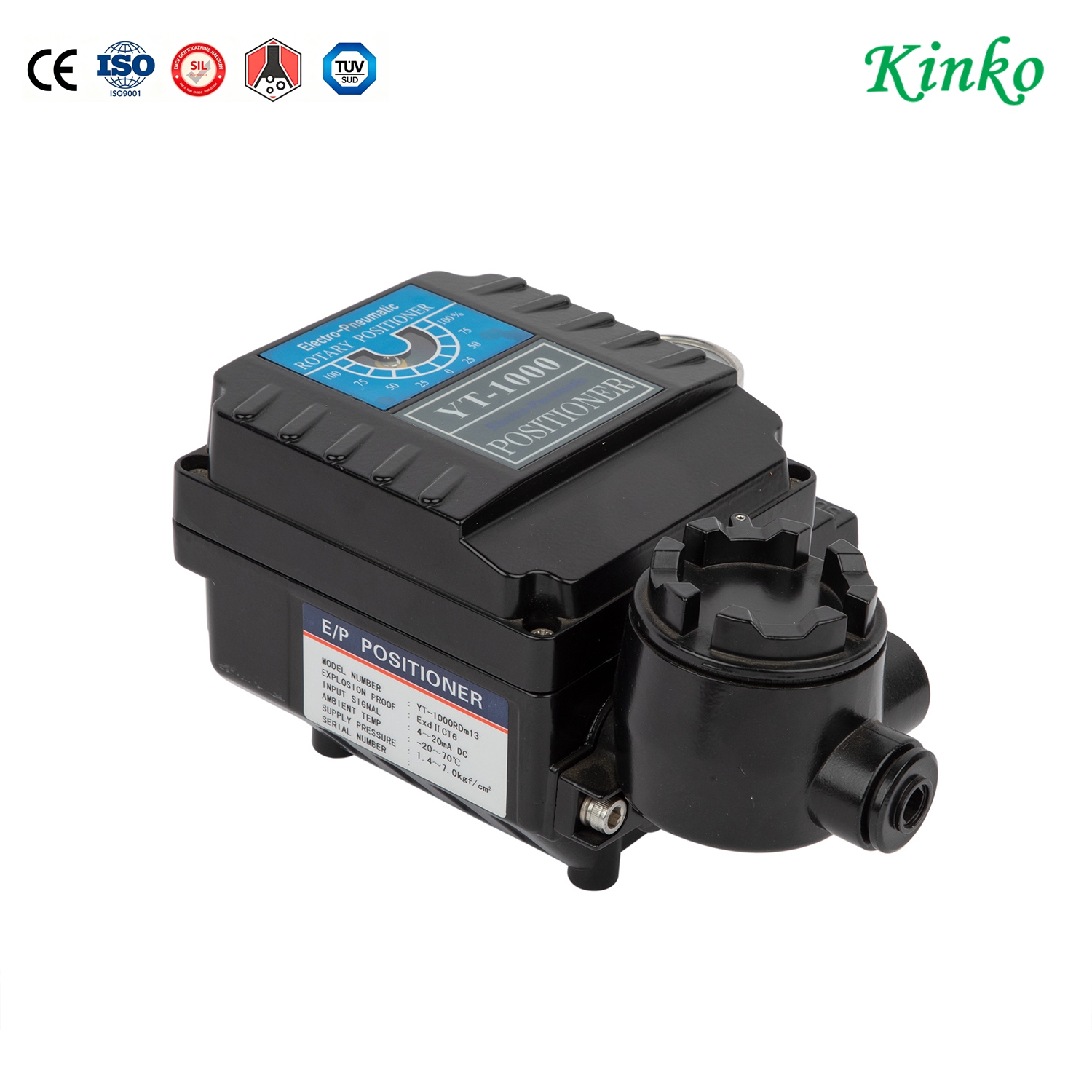
Common YTC Positioner Issues – Diagnosis and Remedies
| Symptom | Likely Cause | Remedy |
|---|---|---|
| Valve does not reach full stroke | Incorrect zero/span; supply pressure low | Re-calibrate; check regulator |
| Valve oscillates / hunts | Gain too high; deadband too narrow | Adjust gain lower; widen deadband |
| Valve drifts from set point | Internal leak in pilot or diaphragm | Inspect and replace seals |
| Slow response | Clogged pilot nozzle; undersized supply | Clean pilot; increase supply line size |
| No output pressure | No input signal; blocked supply; I/P coil failed | Check wiring; check filter; test coil |
| Erratic feedback | Loose linkage; worn potentiometer | Tighten linkage; replace feedback element |
| Condensation inside housing | Failed O-ring; no breather; temperature cycling | Replace seals; install breather membrane |
| Calibration won't hold | Lock screws loose; mechanical wear | Re-calibrate and re-lock; inspect linkage |
Overhaul – When to Rebuild vs. Replace
| Condition | Recommendation |
|---|---|
| Internal seals leaking | Rebuild with seal kit |
| I/P module failed | Replace module (if available) |
| Circuit board damaged | Replace positioner (smart) |
| Housing corroded or cracked | Replace positioner |
| Calibration no longer stable | Replace positioner |
| Cycle count > manufacturer recommendation | Overhaul or replace based on cost comparison |
Ivan (Mobile:+86-18968769287)
WhatsApp:+86-13579991606
Wechat:+86-18968769287
Website:www.kinko-flow.com
ZHEJIANG KINKO FLUID EQUIPMENT CO.,LTD

 info@kinko-flow.com
 +86-133 5611 9006

